USB/LSB for modtagerne/Exciter


Kan man ikke finde et USB filter må man selv i gang. Der er flere forslag på nettet. Vi har valgt denne løsning

Her ombygget til USB/LSB med original filter. USB filter er udskiftet med Telex filter. Så er menu knappen serveret 🙂
Nedenstående er lånt fra nettet
LSB for SAILOR equipment
Frequency generator for LSB on Sailor S1303, R1119 and others.
This site may not get much updated any more, last update 17/06/2003
As long as I worked on the project I placed many updates, but now the final PCB is ready so I leave it to this.
The final circuit is at the bottom of the page, in the first part you can see how I got to it. There are two minor problems you could encounter. The crystal is
running on (too) small capacitors all my junkbox crystals worked fine, but you might find they don’t always start. I encountered an other small problem that
was a leaky 7400, it produced a tiny 597 kHz component in the USB mode, it makes a nasty whistle. It seemed the 5/0 V line was not pulled low enough.
After changing this, it sounded lots better, but keeps having a small whistle. It seems the 7400 itself was just a little leaky, a newer SN74LS00 proved to do a
much better job.
last update April 4 2004.
How it all started.
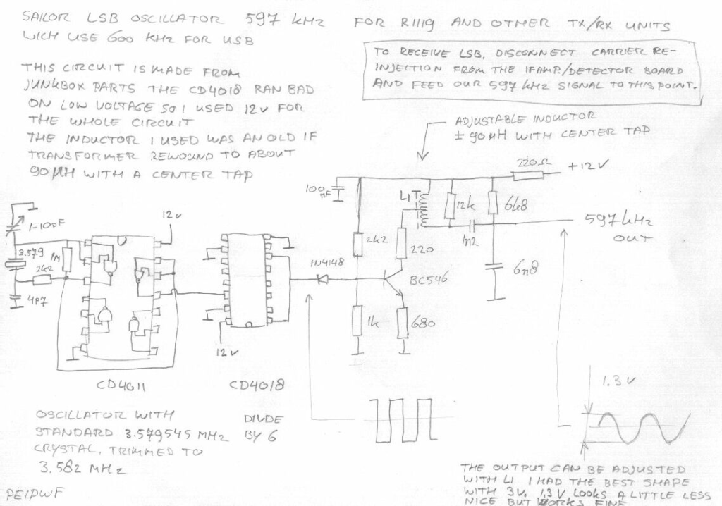
The circuit described here generates 597KHz for carrier reinjection so you can hear LSB signals on for example the Sailor R1119 or other receivers which
use 600KHz reinjection for USB.
This circuit can also be used for S1303 or similar transmitters which use 600KHz for USB generation to make LSB.
One thing has to be kept in mind, due to the 3KHz signal difference also the RX/TX frequency is off by 3 kHz
The solution to this problem seems to be the circuit on the bottom of this page, on this moment I tested this circuit on both my receiver and exciter, it looks
like it’s working fine. I made several contacts on 40m with good reports and on right frequency (display readout = TX/rx QRG).
This is the circuit for 597KHz, I made it out of junkbox parts, so I know there might be improvements, please let me know if you have a nice idea.
Note, You don’t need the sine shaper part of this circuit if directly attach the square wave output to the anode of Diode 102 in the divider module.
If you want to do this, cut loose the diode at the anode side (connected to pin 5 of IC111 74LS390) you van make it switchable or whatever you want. Be
careful with this mod, you should try to damp the output of your 597KHz output, because it is well over 5V.
http://home.wanadoo.nl/e.houwertjes/r1119.html (1 of 8) [18-6-2004 13:50:56]


This is the “final” circuit!
After some weeks experimenting I made this PCB, it generates 597 kHz and changes the programmable divider. so we get LSB signals and correct frequency
read-out.
PDF-file of the circuit/board/layout!
NOTE! for the 7404 in the circuit you HAVE to use a SN74HC04 or SN74HCT04 the 7490 and 7400 can be a quite ordinary SN74LS90 and SN74LS00, I
had used an old SN7400 bot it had some problems switching 597KHz.
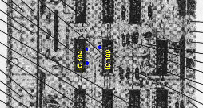
This is the circuit board connected, note the ground is not being used as I solder the board into the tin “fence” in the divider board.
For switching 0/5V I used the mode switch on “TELEX” I used the 18V of this switch and a voltage divider 1k5/270ohm to switch 0/3V (3v looks enough
like 5V)
The PCB track between pin6(IC104) and pin9(ic109) has to be cut. this is on the bottom side of the PCB, so I just cut pin9 just above the PCB.
The small blue diode in the picture is cut at the IC-side this IC-pin connect to 600KHz input of our PCB, the loose end of the diode connects to 600/597 kHz
out.
http://home.wanadoo.nl/e.houwertjes/r1119.html (4 of 8) [18-6-2004 13:50:56]
3 svar
Hej,
Jeg er nu også blevet smittet af Sailor-virussen.
Jeg har to styk R1119 og en exciter plus 400w sender med indbygget PSU.
Desuden en masse PCB, normalt fra 1000-serien.
En af R1119 har en defekt VCO (1200)
Spørgsmålet er, om du også leverer/sælger dele.
Altså en fungerende VCO.
Hilsen,
Jack
PC0RTA
Holland
Hej jack
Kan godt hjælpe med en VCO 1200
skal lige teste dem.
Bo
[…] Se tidligere indslag er om LSB filter […]